Hardware
- Raspberry Pi Model B+ V1.2 with Debian 11.4
- ARDUINO Mega Rev. 3
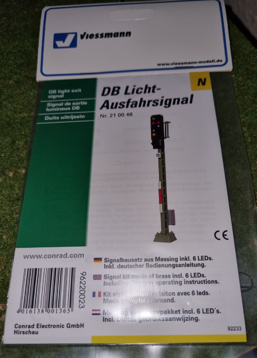
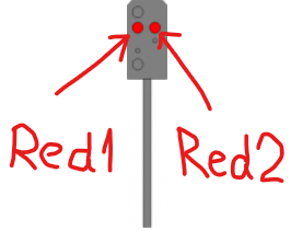
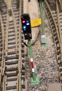
And this nice signal kit (DB Licht-Ausfahrsignal), presumably produced by Viessmann for a famous german online shop:
Software
- Rocrail “Iron” 2.1.2609 [DAILY] [Sep 8 2022 04:00:18]
- DCC++ EX installed on Arduino UNO (DCC-EX V-4.1.1 rc3)
Let’s get our hands dirty
Configure DCC++ EX
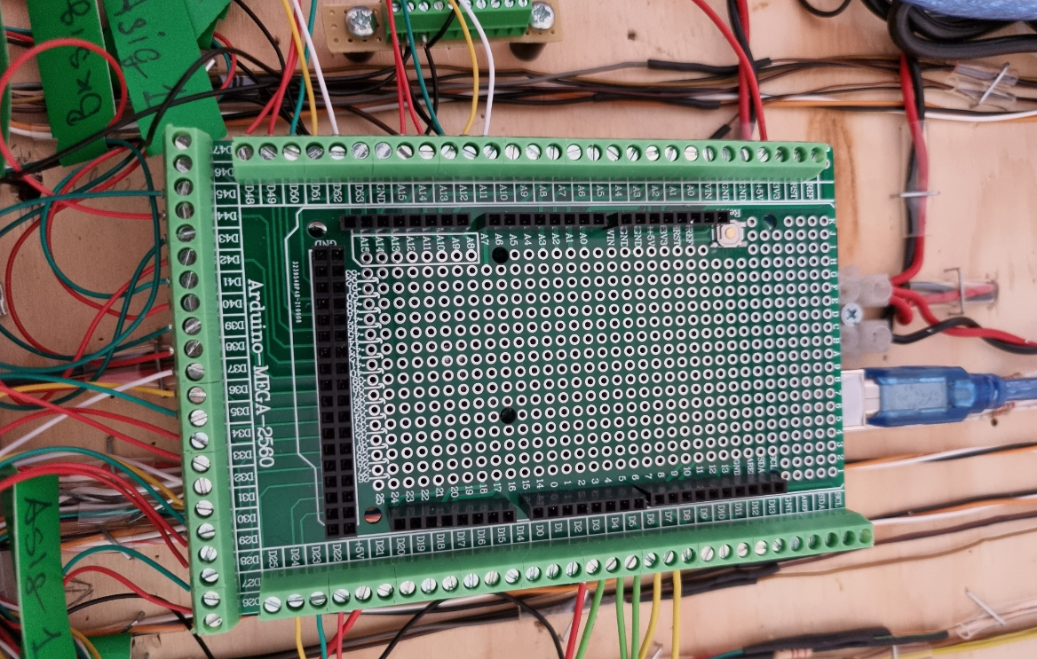
After I assembled the signal, I connected it to the digital outputs on the Arduino UNO. Here is this lovely pic of it with several other signals connected:
The first step is to set up the outputs on the Arduino board. I did it directly via terminal; after spending some time trying to do it via Rocarail, I gave up. This can be done for example with this command:
picocom -b 115200 -r -l /dev/ttyACM1 -c
Let’s say, to configure output 69 we need to do the following:
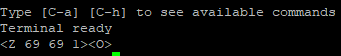
Accordingly to the DCC++ EX command reference, this will set up port 69 with the name 69 configured for an inverted operation, i.e. ACTIVE=LOW / INACTIVE=HIGH. The reason for the latter is that the common black wire of the signal has to be attached to the ‘+’ line. This can also be tested like this:
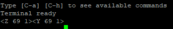
If everything is done right, the respective LED will be turned on. Needless to say, the Rocrail process has to be stopped, before you connect to Arduino via terminal. Another pitfall might be the name of the USB port; it was /dev/ttyACM1 in my case, but better to experiment a bit to be certain.
Signalwesen
This was actually the name of the very useful page on the Rocrail site with a detailed explanation about signals and such. I allowed myself to grab the below piece of information, which explains how an exit signal works from this site:
| Signal | Picture | LEDs |
|---|---|---|
| Hp0 | Red1 + Red2 | |
| Hp1 | Green | |
| Hp2 | Green + Yellow | |
| Sh1 | Red1 + White |
So far so good; our signal has 5 LEDs and the above table tells us, what LEDs to turn on and off to implement every four aspects.
Rocrail configuration
The challenge here is that in the Rocrail signal setup dialogue, there are only four fields to specify addresses of signal LEDs and we need five. After some reading, I came up with two ideas – split a signal into two or configure four LEDs directly and use Action to control the fifth. I haven’t tried the first and went ahead with the latter.
Looking at the table above I decided to control the left red LED via Actions, it would be Red1 in the above table. And here is the picture:
Let’s start with the set-up:
For the RED address, I used the output number to which the “right” red LED is connected. Next one is a bit less straightforward:
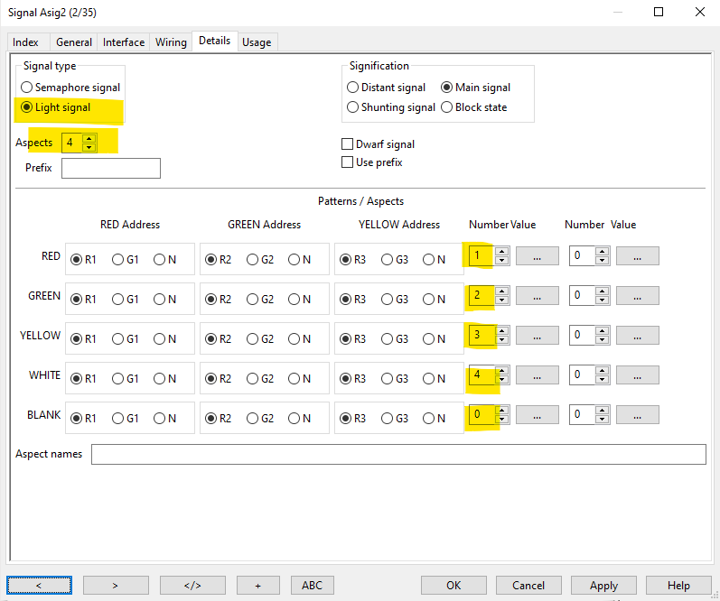
In the first “Number” column I just put the aspect numbers, 1 to 4. Let’s assume they will represent the signals from the above table: 1 – Hp0, 2 – Hp1, 3 – Hp2, 4 – Sh1. Then use the 3-dot button to the right to get to this dialogue:
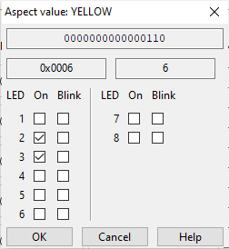
This is the aspect #3, i.e. Hp1. Look at the binary representation in the first field at the top – 0000000000000110. And compare it to the colour sequence WHITE:YELLOW:GREEN:RED. LEDs 2 and 3 will go up, i.e. YELLOW and GREEN. And the below picture is for Aspect #4 – Sh1 (White):
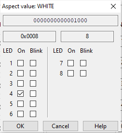
Why white? Just because the 4-th digit from the right is “1”. Simple, isn’t it? 😉
Curiouser and curiouser!
The previous step was kind of tricky but now looks very simple, after I got a grip on it. The next step is to set up Actions to control Red1 LED (left red).
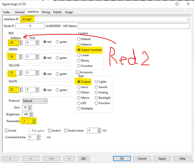
First, we need to define a new output, which will control our Red1 LED:
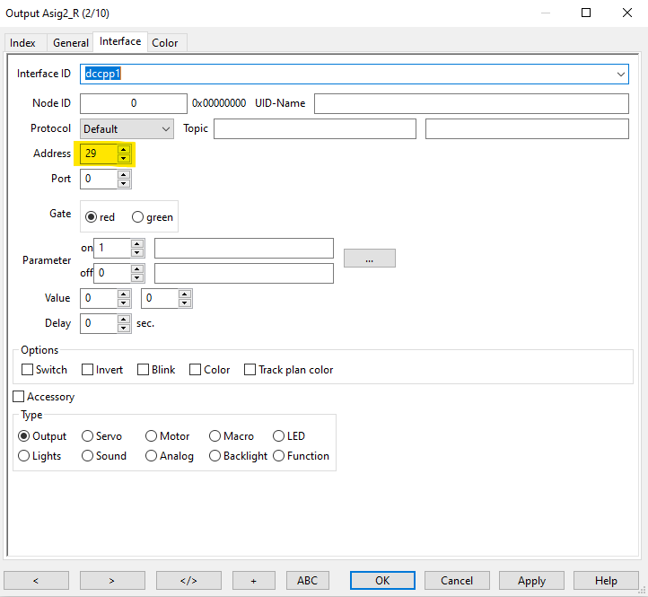
The address 28 is the output number of the Arduino board, our Red 1 LED is connected to. Also, note that a new output will appear on the track plan picture. With that, let’s go and get two actions defined to turn it on and off:
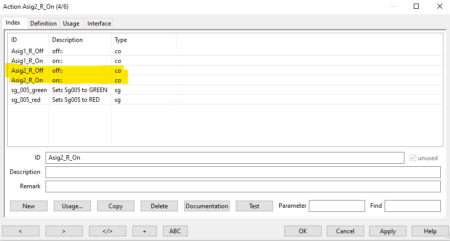
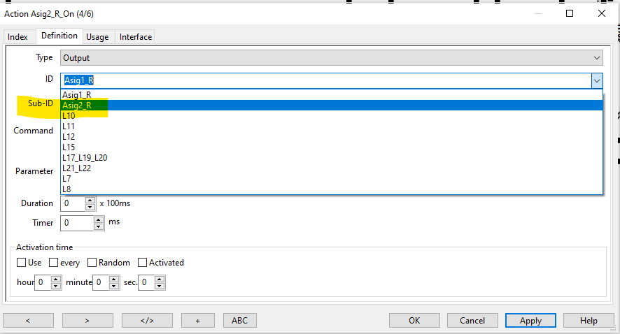
Action definition is rather simple, just the right output has to be selected from the drop-down:
We are almost there. Next, we need to go back to the signal definition and hit the “Actions…” button on its general tab:
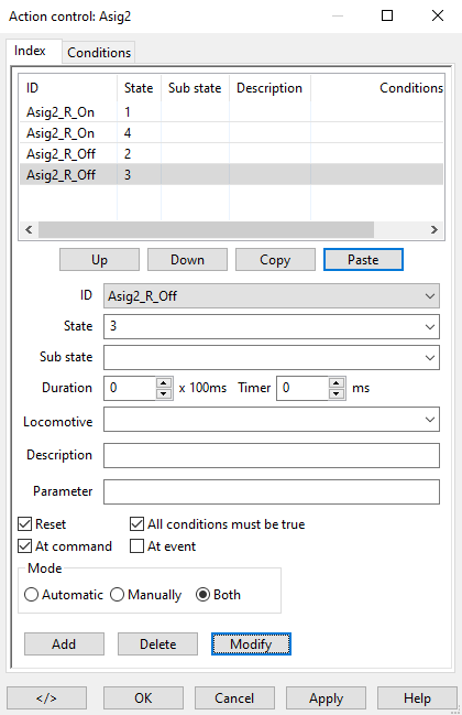
Here we define action controls. We have our 4 aspects and what actions to be taken, when the signal switch to the respective aspect. For 1 (Hp0) and 4 (Sh1) we turn the left Red LED on and for 2 (Hp1) and 3 (Hp2) we turn it off.
It’s a wrap
This is actually it; below is the Sh1 aspect:
Caveats
One thing was really annoying, and I couldn’t establish any pattern. It seems like Rocrail is trying to redefine the outputs on the Arduino Mega from time to time. So, the final step should be to verify and correct the output configuration. Specifically, watch for the pins that have names different from their numbers. In such a case it looks like <Z 24 25 1>.